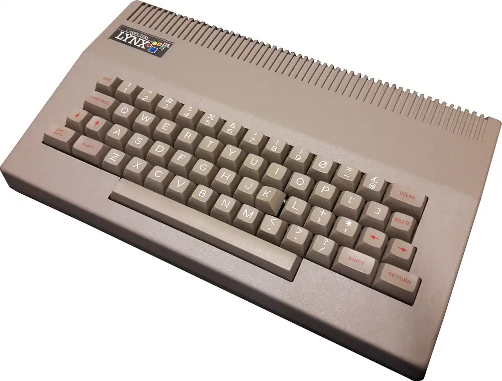

The Camputers Lynx 128, the highest-end model of the Camputers Lynx family produced by Camputers, was released in December 1983.
The Lynx line had appeared earlier that same year with the 48 KB model in March 1983, followed by the 96 KB version around September 1983. The 128 KB machine arrived later as a significantly revised design intended for more serious or business use. The Lynx 128 was later renamed to Laureate
Technically, the Lynx 128 differed from the earlier models in several ways:
- It used a faster 6 MHz Z80B processor instead of the 4 MHz Z80A used in the 48 KB and 96 KB machines.
- It had 128 KB of RAM and a new motherboard design.
- It added an 80-column text mode and was designed to run CP/M 2.2 with optional floppy disk drives.
- Because of the architectural changes, it was not completely software-compatible with programs written for the earlier Lynx models.
The Lynx 128 appeared only a few months before the company collapsed in June 1984, so relatively few units were produced compared with the earlier models.
The Camputers Lynx had one of the more unusual memory and video architectures among early 1980s home computers. While it used a conventional Zilog Z80 CPU, the way memory and graphics were organized made the machine powerful on paper but awkward to program. The system contained 96 KB of RAM, even though the Z80 could only address 64 KB at a time. To solve this, the Lynx used bank switching, where different portions of RAM could be swapped into the CPU’s address space. However, the video system also needed access to RAM at the same time, so the computer had to constantly switch which memory bank the CPU or video circuitry could see.
The graphics system was tightly tied to this bank-switched memory. Instead of having a separate, dedicated video RAM block like many contemporaries, the Lynx used main RAM for its frame buffer. The video controller—based on the Motorola 6845—read the display directly from system memory while the CPU was also trying to access it. To avoid conflicts, the machine implemented a scheme where the CPU and video hardware alternated access to memory. This effectively slowed down memory access and made graphics operations more complicated than on many competing systems.
Another unusual aspect was the bit-mapped display layout. The Lynx supported a fairly advanced resolution for the time (around 256×248 pixels with up to 8 colours), but pixels were arranged in memory in a non-linear pattern tied to the 6845’s addressing scheme. The colour information was stored in separate memory structures, so plotting a single pixel could require manipulating multiple memory locations and bit masks. As a result, simple graphics operations—such as drawing lines or moving sprites—often required more CPU work than on machines like the Sinclair ZX Spectrum or BBC Micro.
In practice, the architecture gave the Lynx excellent theoretical graphics capability, but the complexity of bank switching and the unusual memory layout meant software developers had to write highly specialized routines to achieve good performance. Because the system arrived late in the UK home-computer market and had a small installed base, relatively few programmers invested the effort required to exploit the hardware fully. This contributed to the machine’s reputation as technically interesting but commercially unsuccessful.
Camputers LYNX-OS
The Camputers Lynx, released in 1983, did not employ a traditional operating system in the sense of disk-based microcomputers. Instead, its software environment was built around a resident monitor and BASIC interpreter stored in ROM. This ROM-based environment provided direct machine-level control, memory management routines, and I/O handling for the keyboard, display, and tape storage. The Lynx’s Z80A CPU operated with a segmented memory map supporting up to 192 KB, divided into 64 KB banks that could be switched in and out, and the firmware contained the fundamental routines for bank switching and peripheral access.
Program execution on the Lynx OS-level environment was mediated through the ROM monitor, which offered hooks into low-level system calls for tape I/O, screen control, and keyboard scanning. Unlike systems with CP/M or MS-DOS, the Lynx’s “OS” was not file-oriented; instead, programs were stored sequentially on cassette tapes, with the ROM providing routines for encoding, decoding, and synchronization. Disk expansion systems were later introduced, and with them came third-party CP/M compatibility layers, but the base machine remained tied to the resident monitor and BASIC environment.
From a system software perspective, the Lynx firmware’s structure emphasized modularity, with jump tables and memory-resident vectors for core routines. This allowed extensions such as disk controllers or third-party ROMs to integrate new functionality by replacing or intercepting existing vectors. The BASIC interpreter itself was tightly coupled to these routines, offering access to graphics, sound, and bank-switched memory directly through language extensions. As a result, the Lynx “OS” can be described as a minimalist, ROM-based firmware environment providing primitive multitasking only in the sense of interrupt-driven device handling, with extensibility dependent on hardware add-ons and patched ROM modules.
Motorola MC6845 Video Display Generator
The Motorola MC6845 commonly referred to as a CRTC (Cathode Ray Tube Controller) served as the architectural backbone for the video subsystems of many iconic 8-bit computers, including the IBM PC (CGA/MDA) and the BBC Micro. Unlike modern GPUs that handle complex rendering, the MC6845 was a programmable timing generator. Its primary function was to manage the synchronization signals (HSYNC and VSYNC) and generate the memory addresses required to fetch pixel or character data from video RAM. By offloading these repetitive timing tasks from the CPU, it allowed for flexible display formats through a set of 18 internal 8-bit registers.
At its core, the chip operates using a series of internal counters that track the horizontal and vertical position of the electron beam. The programmer defines the display geometry by writing to registers that control the total number of horizontal characters, the horizontal displayed characters, and the sync pulse widths. This programmability allowed developers to implement various "tricks," such as hardware scrolling or split-screen effects, by manipulating the Start Address Register (R12 and R13) mid-frame. This changed which part of the video memory the controller pointed to at the beginning of a raster scan.
The interface between the MC6845 and the system memory is fundamentally passive regarding data content. The controller outputs a Memory Address (MA0–MA13) and Row Address (RA0–RA4) but it does not actually "see" the data being fetched. In a typical character-mapped configuration, the MA lines point to the character code in RAM, while the RA lines determine which specific scanline of that character is being pulled from a Font ROM. This separation of concerns made it highly versatile, supporting both alphanumeric modes and "all-points-addressable" (APA) graphics modes depending on how the external logic interpreted the address lines.
Timing and synchronization are governed by the Character Clock (CLK) input, which increments the internal horizontal counter. To prevent "snow" or visual artifacts, the system must carefully manage bus contention between the CPU and the MC6845, as both require access to the video RAM. This was often solved using "interleaved" access, where the CPU and CRTC traded cycles, or by restricting CPU writes to the vertical blanking interval. The chip's ability to provide a Light Pen strobe input further expanded its utility, allowing the hardware to latch the current memory address when a light pen hit was detected, providing a primitive but effective form of user interaction.
Programming the MC6845 Video Display Generator
To program the MC6845 for a specific resolution, you must calculate the values for its internal registers based on your system's Character Clock (CLK) and the target monitor's refresh rates. The chip operates by counting character units rather than individual pixels, so your first step is determining how many pixels wide a "character" is (typically 8) to find your horizontal frequency.
1. Horizontal Timing Registers (R0–R3)
These registers define the width of the scanline and the position of the horizontal sync pulse (HSYNC).- R0 (Horizontal Total): The total number of character clocks in a full scanline, including the visible area and the "overscan/blanking" period.
- R1 (Horizontal Displayed): The number of characters actually shown on the screen (e.g., 40 or 80).
- R2 (Horizontal Sync Position): This determines where the sync pulse starts. Moving this value shifts the entire image left or right on the monitor.
- R3 (Sync Width): Defines the duration of the HSYNC pulse in character clock units.
2. Vertical Timing Registers (R4–R7)
Vertical timing is measured in character rows not individual scanlines.- R4 (Vertical Total): The total number of character rows in a frame.
- R5 (Vertical Total Adjust): A "fine-tuning" register that adds a specific number of scanlines to the end of a frame to reach exactly 50Hz or 60Hz if the character rows don't divide perfectly.
- R6 (Vertical Displayed): The number of visible rows on the screen (e.g., 25).
- R7 (Vertical Sync Position): Determines the vertical start of the sync pulse, effectively moving the image up or down.
3. Character and Scanline Control (R9–R11)
The MC6845 needs to know the physical "height" of your characters to correctly increment its addresses.- R9 (Maximum Scan Line Address): This tells the chip how many scanlines make up one character row (e.g., 7 for an 8-pixel high character, as the count starts at 0).
- R10 & R11 (Cursor Control): These define which scanlines within a character block the cursor occupies and whether it should blink.
4. Memory Mapping (R12–R13)
These are the Start Address Registers They determine which byte in your Video RAM corresponds to the very first character at the top-left of the screen. By changing these values during a "Vertical Blank" period, you can achieve Hardware Scrolling If you increment the start address by the width of one row, the screen appears to jump up instantly without the CPU having to move a single byte of data in memory.CPU - The Zilog Z80
The Z80 quickly became popular in the personal computer market, with many early personal computers, such as the TRS-80 and Sinclair ZX80, using the Z80 as their central processing unit (CPU). It was also widely used in home computers, such as the MSX range, SORD, and the Amstrad CPC, as well as in many arcade games. Additionally, it was also used in other applications such as industrial control systems, and embedded systems. The Z80 was widely used until the mid-1980s, when it was gradually replaced by newer microprocessors such as the Intel 80286 and the Motorola 68000.
The Z80 microprocessor was developed by Zilog, a company founded by Federico Faggin in 1974. The Z80 was released in July 1976, as a successor to the Intel 8080. It was designed to be fully compatible with the 8080, but also included new features such as an improved instruction set, more powerful interrupts, and a more sophisticated memory management system.
Originally the Z80 was intended for use in embedded systems, just as the 8080 CPU. But the combination of compatibility, superior performance to other CPUs of the era, and the affordability led to a widespread use in arcade video game systems, and later in home computers such as the Osborne 1, TRS-80, ColecoVision, ZX Spectrum, MSX, Sega's Master System and many more. The Z-80 ran the original Pac-Man arcade cabinet. The Z-80 was used even in the Game Gear (1990s), and the TI-81 and succeeding graphic calculators.
The Z-80 remained in production until June of 2024, 48 years after its original release. Zilog replaced the processor with its successor the eZ80, an 8-bit microprocessor that features expanded memory addressing up to 16 megabytes, and running up to 50MHz, comparable to a Z80 clocked at 150MHz.

RAM max: 192kB
ROM: 20kB
VRAM: Shared
Tape
optional 5.25" FDD