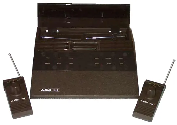

Atari 2700
The Atari 2700 was a prototype that was intended to be the successor of the Atari 2600. It was fully compatible with the 2600, but had wireless controllers, touch-sensitive switches and a more stylish case. The controllers had retractable antenna's and could be stored inside the console itself. The controllers operated via radio signals and were powered by a 9-volt battery. In addition, the unit also contained two standard Atari 9-pin controller connectors so the user could still use third party joysticks, paddles and other devices that connected to those ports.
The case featured a cartridge slot and touch sensitive buttons. It also had a row of LEDs that indicated which controllers were plugged in, and buttons that could switch the controllers between joystick and paddle mode.
Due to problems with radio interference, and range that the team could not resolve, the Atari 2700 never saw the light. The range of the controllers was about 1000 feet, but there was no pairing between the console and the controllers, so any controller could operate any device. For neighbors that both had a 2700, this could be problematic. The technical design of the controllers was based on garage door openers, causing interference, and one could accidentally open a garage door while playing a game.
The case design became the model for the later Atari consoles, the Atari 2800, the Junior, the 5200 and the 7800.
CPU - The Motorola 6507
The MOS Technology 6507 CPU is an 8-bit microprocessor based on the 6502 technology. Basically it is a 6502 packaged in a 28-pin DIP instead of a 40-pin. This made the chip cheaper to package and integrate in systems. MOS technology achieved this by reducing the address bus from 16 bits to 13 bits and removing a number of other pins used only for certain applications.
The 6507 is the main chip of the Atari-2600 family of consoles. The Chip was launched in 1975 and could, due to the reduced number of address pins, address 8KByte of memory. This proved to be enough for the Atari consoles and for peripherals such as the 850 Serial & Parallel Interface, the 1050 disk drives and more.
Atari Player Missile Graphics
The Atari Player-Missile Graphics (PMG) system was not a framebuffer in the modern sense but a set of time-critical shift registers built directly into the TIA (Television Interface Adapter) chip. It provided five independent movable objects: two "players," two "missiles," and one "ball." Each player was an 8-bit wide pattern register that could be shifted horizontally by writing to horizontal motion registers, and the missiles were single-bit wide objects with optional width expansion (2× or 4×). The ball was also a single-bit wide object but could be stretched up to 8 pixels. These objects were rendered in hardware in parallel with the background playfield, and their pixels were combined by priority logic to form the final composite video signal line by line. Unlike bitmap systems, no RAM buffer existed for sprite graphics—the CPU had to continually update the pattern registers at precise cycle counts if animation or varied shapes were required.
Synchronization with the television raster was crucial. The 6507 CPU executed instructions at 1.19 MHz, and each NTSC scanline consumed 76 CPU cycles. Developers had to time updates to the TIA registers so that the correct player/missile graphics appeared at the right horizontal positions. Horizontal positioning itself used a mechanism called "HMOVE," where writes to motion registers triggered a fine shift of the object relative to the color clock. To display more than two players per line, programmers resorted to "racing the beam," rewriting the player graphics mid-scanline or between scanlines to reuse the same hardware objects multiple times. This demanded cycle-accurate programming, often with unrolled loops or carefully aligned instruction sequences, to ensure that TIA updates coincided exactly with the raster beam.
The PMG system’s integration with collision detection further defined gameplay mechanics. The TIA contained hardware latches that reported collisions between any combination of players, missiles, the ball, and the playfield. Reading the collision registers gave the CPU instantaneous results without requiring software-based pixel overlap tests. This allowed real-time detection of events like a missile hitting a player, which was essential given the limited CPU resources. However, the narrow data path—1-bit missiles and balls, 8-bit players—and absence of automatic buffering imposed strict design constraints. Game graphics relied heavily on flicker techniques, multiplexing, and creative use of repeated patterns. Thus, the Atari PMG system exemplifies a minimal but highly deterministic hardware sprite engine, optimized for cost, that forced programmers to directly master scanline timing and low-level hardware interaction.